
© 1999 Chris Santucci ALL RIGHTS RESERVED
by
Chris Santucci
The camera base is 7″ X 3 5/8″ X 1″ Poplar. It has to have the front corners shaved down to allow for the angle of the 1X2’s that get screwed into it (I used drywall screws, 2 on each side). Also a hole is drilled into the base to allow for mounting the camera with a thumbscrew. The hole is just large enough to move the camera around for balancing.
The lower section gets screwed into the 2 upper arms (1″ X 2″ pine) with a total of 4 screws (2 on each side), and I pilot drilled each screw hole (it’s only pine).
The joints were all reinforced with Fiberglass cloth and resin that can be purchased at an auto parts store.
I glued a spirit level on the base to enable balancing, which you’ll have to do by mounting the unit at the handle to something that’s not moving. Leave the camera mounting thumbscrew a little loose with the camera on the unit, then swing the unit fore and aft. Watch the level and determine whether or not to shift the camera either way to achieve level from that axis. Then swing the unit from side to side and watch where the bubble ends up. Shift the camera either way to achieve level from that axis. Then all you have to do is tighten the thumbscrew, and your ready to go.
The camera mounting hole starts at 3/4″ from the long side of the base, and 1 5/8″ from the back of the base. The hole itself is 3/4″ wide and 2 1/4″ long.
The handle is the most crucial part, and all I used was a hinge. It’s one of those hybrid hinges that has a strap coming off of it (for lack of a better description). I used a piece of railing post (hardwood), and cut a groove into the top (1 1/2″ deep). The strap end of the hinge was cut down to 1 1/2″ also, and rounded off. I also filed this half of the hing on both sides to make it flat and smooth. The hole in the handle that goes through a hole (you’ll have to drill in the hinge) is exactly 1 1/2″ from the top, and I used a brass woodscrew (#12 X 2 1/2″) cut down to fit the handle. The pilot hole for this screw will have to allow for the larger end of the screw to fit snugly, not tight, maybe even a little loose. The groove in the handle allows the hinge to fit in loosely, when the woodscrew is screwed in snugly.
Here’s the crucial part. Friction at the 2 axis of the hinge need to be minimized as much as possible. I used some furniture polish for the inside of the groove in the handle, and that hole where the woodscrew goes through the hings needs to be a little loose. I am planning on putting a dab of teflon grease in that hole, which should give me less friction. The other part of the hinge has some kind of nylon insert which seems to provide low friction. Look for that kind of hinge.
I got most of my materials at Home Depot.
The counterweight is a scuba, weight-belt weight. I think it weighs about 2 1/2 pounds. I think. It’s slid onto a piece of aluminum extrusion that is screwed onto the lower section. It’s snug, and it can be swung to either side to allow for another balancing option.
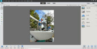
The monitor is just what it looks like. A low cost Citizen LCD monitor. If anyone can find out where an Active Matrix screen can be found, please let me know. This one is not that bright.
I am currently updating this unit by putting a rechargeable battery pack down where the counterweight is. I will then plug the monitor and the camera into that box. As it is, the camera still has it’s battery, and the monitor also keeps it’s battery. I also have used this unit with the viewfinder and the microphone attached.
As far as using the unit goes, you’ll have to practice. It’s very stable, but there are some things to work out when you practice. I have found the need to use my free hand to damp the movements of the unit on occasion. You’ll see.
If anyone fools around with this design and arrives at some ways to improve it, please let me know.
Good Luck. Chris ([email protected]).


THANK YOU !!!
THANK YOU !!
THANK YOU !