by Hal Landen
With Special Thanks To Larry Jandro, LJ Video Engineering and Rentals.
Composite Video Signal
Waveform Monitor
Vectorscope
Proc Amp
THE VIDEO SIGNAL
In the U.S., the video picture is composed of 525 horizontal lines. These lines are created by a beam of electrons that write the lines one at a time on a picture tube. When the beam has sprayed 525 of the lines, the viewer sees one still frame of a video picture. The illusion of motion is then created by repeating this process 30 times each second. Each of the 30 frames is a still image, but each shows a progressively different stage of the motion.
It’s really like watching a slide show in fast motion. You’re seeing 30 stills every second, but they blur together in your mind’s eye to produce the illusion of motion. This little trick is called “persistence of vision.” Without it, neither motion pictures nor video would exist.
The scanning electron beam starts at the top left of the picture tube and writes one horizontal line. Then when it reaches the right hand side of the picture or raster area, the beam drops down and writes the next line from left to right. In the early television systems, this process of writing 525 lines for each frame created noticeable flickering. To minimize the flicker, engineers developed a system of “interlaced scanning.”
The interlace system divides each frame into two separate fields each with half of the picture information for a total of 525 lines of picture information. The first field contains all odd- numbered lines #1, #3, and so on. The second field contains the even numbered fields #2, #4, etc.
After field one is scanned for all the odd-numbered lines, a vertical synchronization pulse returns the electron beam to the top center of the picture tube and then scans all of the even numbered lines. Each of the 30 frames of a video picture includes these two interlaced fields so the actual scanning rate is 60 fields per second.
In countries that adhere to the NTSC conventions (National Television Standards Committee), there are seven types of electronic information that comprise the video image. Together they are called the television composite waveform, more commonly referred to as composite video.
The Composite Video Signal
The seven elements of the composite video signal include:
horizontal line sync pulse
color reference burst
reference black level
picture luminance information
color saturation information
color hue information
vertical sync pulse
Horizontal Line Sync Pulse
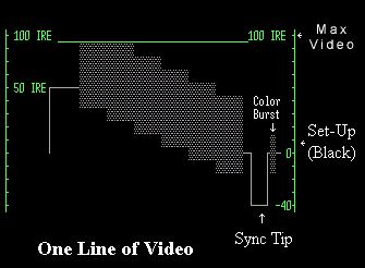
Before each line is scanned, horizontal sync pulses set the electron beam to a locked position so that each line of picture information starts at the same position during scanning.
Color Reference Burst
To insure standard hue and color saturation, a 3.58 megahertz color reference burst is added before the picture information on each scan line. It is a sine wave with eight to nine cycles. Its phase is set at zero degrees.
Reference Black Level
Black level is also called “setup” or “pedestal.” It is defined as 7.5 IEEE units (from the Institute of Electrical and Electronics Engineers referred to as “Eye triple E.”) Formerly these units were called IRE units from the Institute of Radio Engineers.
Picture Luminance Information
Picture Luminance ranges from 7.5 IEEE units for black to 100 IEEE units for peak white.
Color Saturation
Color information is interleaved with the picture luminance information. This is called the 3.58 megahertz subcarrier. The saturation of the colors is determined by the amplitude of the subcarrier. The hue of the color is determined by comparing the phase of the subcarrier with the phase of the Color Reference Burst (see above.)
Color Hue
Color hue is also present in the 3.58 megahertz subcarrier. The accuracy of colors in the picture are determined by the phase or rotation of the color hue information.
Vertical Sync Pulse
The vertical sync pulse controls the length of time of the vertical blanking interval. This is the period when the TV screen goes blank between the end of one field and the beginning of the second field. The vertical blanking interval is sometimes used for inserting time code, automatic color tuning and captioning information in the video signal.
There is also a horizontal blanking interval which occurs between the end of one scan line and the beginning of the next. This blanking interval is controlled by the horizontal sync pulse. Within this interval are the horizontal sync pulse and the color reference burst.
THE WAVEFORM MONITOR
To see the various elements of the composite video signal two special test oscilloscopes are used – the waveform monitor and the vectorscope. The waveform monitor displays the black and white (luminance) video signal information. With it you can analyze and improve the video signal. It allows you to analyze the information from an entire frame or from just one line of video. The waveform monitor displays the signal on a scale like this:
+ 100 ———————
7.5 ———————
0 ———————
– 40 ———————
By viewing the video signal on this scale, you can modify any signal that goes above the 100 mark or below the 7.5. Signals that are outside of this range lose all detail so that if a light colored face is at or above 100 units, it will be washed out. A dark colored face below 7.5 units will be so dark as to have no detail. Faces in the +50 to +80 range are generally considered to be properly exposed.
Here’s what color bars look like on a waveform monitor:

Color bars on a waveform monitor.
The waveform monitor is especially helpful in two phases of video production: shooting and online editing. For the shooter you might wonder why you couldn’t just look at a standard video monitor to see if your picture looked alright. The problem is that the picture monitor is not a reliable guide to the picture you are recording or to how that picture will look in the finished videotape.
When used with a video camera, the waveform monitor is a reliable guide to exposure. If the average value of important information in the picture is over 100 or under 7.5 IEEE units, the exposure is off. This exposure can be adjusted by changing the camera’s aperture and/or by adding more or less light to the scene.
In an online edit session the waveform monitor works the same way only this time it measures the values of images from videotape or other online devices like character generators or special effects generators.
THE VECTORSCOPE
Typically used in conjunction with the waveform monitor, this scope displays and measures the chrominance (color) of the video signal. The scale of the vectorscope is a circle overlaid with the color amplitude and phase relationship of the three primary colors (red, green and blue). In the center of this circle graph is the luminance (black and white) value of the signal. Through this center point, three axes represent the primary colors.
If you pointed your camera at a white card, the vectorscope would display a dot in the center. If this dot is off center, the white card would not be recorded as pure white, but with a tint of color. To record the white as white, the camera operator must use the camera’s White Balance Control. The camera can also be adjusted internally with the red and blue gain control. On the vectorscope this would be adjusted until the signal on the scope were dead center and not favoring red, blue or green.
In the online edit session, the vectorscope determines the proper colors through the use of Color Bars. The standard procedure is for the camera operator to record 60 seconds of color bars at the beginning of every tape. This insures that when edited, the colors will be the same from tape to tape and from any effects that are generated in the online editing session.
THE PROCESSING AMPLIFIER
Called a proc amp, this device can modify both the chroma and luminance values of the video signal. The proc amp should be used with both a waveform monitor and vectorscope to insure that the changes you are making are what you think you are making. Think how TV set operates. By adjusting color, contrast and the other controls, you can change the appearance of the picture. But you are not changing the source of that picture – whether it be from a camera, videotape or broadcast. You are only changing the display of that signal.
The proc amp lets you change the actual signal rather than just the display. So if the proc amp were used in an edit session between the source VCR and the record VCR, you would change what happens to the tape in the record VCR. Want less color saturation on your master edit tape? Just turn down the proc amp’s chroma gain control.
The proc amp can be an invaluable tool for correcting the color and luminance elements of a video signal. However, it must be used in conjunction with a waveform monitor and vectorscope for predictable results.
Until you see the video signals actually displayed in this manner, this may seem too complicated. But the first time you venture into a properly equipped editing studio, an engineer or editor will demonstrate what the signal looks like on this test equipment. When you see it in action, you’ll have an immediate understanding of what it means. And especially how you can improve the colors, contrast and exposure of your edited tape. You’ll instantly see when a shot is overexposed and how much you can correct it. There’s a lot more to the video signal, but this basic introduction should help you make better videos.
If, however, you are not changing the video signal because you are working with a basic editing system without any additional equipment, then except for degradations caused by generation loss, the colors and luminance of your edited tape should be the same as your source tape. The controls at your disposal are in white balancing (and black balancing) your camera and in recording color bars.


Good article, thanks for share it.
cool information. explained in the most “humane” way possible to the beginners like me. hope u could explain how the 7.5 IRE relates to the waveform monitors in the NLEs like Sony Vegas…..seen couple of articles that advice to have the black at Zero on these NLE waveform monitors.aka “crushing the blacks” technique.
ok
we are manufactures of video surv gear; we have recently switched to high res, color to black n white, low light pin hole cameras; we are having a heck of a time getting them to be consistent; with an auto iris, understand direct sun light may affect them, but sunny days, non direct?/ this is what we are experiencing? any suggestions etc? tks much!! kevin
Hi Hal. Great overview of the format. Just a couple quibbles I would like to mention. You said “30 stills every second” which is not quite true. It’s actually 60 stills (or 59.94…) per second b/c every image is different. 30 stills is if NOTHING in the image is moving but with live interlace cameras you have 60 different images (interlaced) per sec. The other issue is the 7 parts in the NTSC signal, you mentioned “black reference” but that only exists in countries that don’t use a signal called “pedestal” for black. The term we use in the US is “blanking level” (0 ire) and this causes no end of confusion when a Japanese program comes to the US or visa versa as Japan doesn’t use this pedestal signal. Hence the need for pluge bars in the colorbar signal. Hope this makes sense.